 English
 Espaol
 Franais
 阿拉伯
阿拉伯 中文
中文 Deutsch
 Italiano
 Português
 日本
日本 韓國
韓國 български
 hrvatski
 esky
esky Dansk
Dansk Nederlands
 suomi
suomi Ελληνικ
 印度
印度 norsk
norsk Polski
 Roman
Roman русский
 Svenska
Perkins珀金斯900 3.152柴油發動機2643 B134燃料噴射泵供應商,Perkins珀金斯900 3.152柴油發動機2643 B134燃料噴射泵技術價格規格咨詢服務,Perkins珀金斯900 3.152柴油發動機2643 B134燃料噴射泵零配件供應,Perkins珀金斯900 3.152柴油發動機2643 B134燃料噴射泵售后服務中心,Perkins珀金斯900 3.152柴油發動機2643 B134燃料噴射泵,Perkins珀金斯900 3.152柴油發動機2643 B134燃料噴射泵詳細的技術參數,

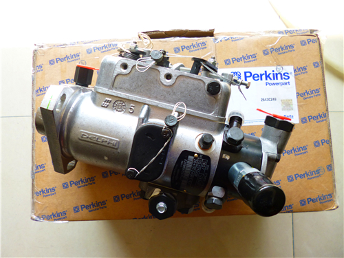
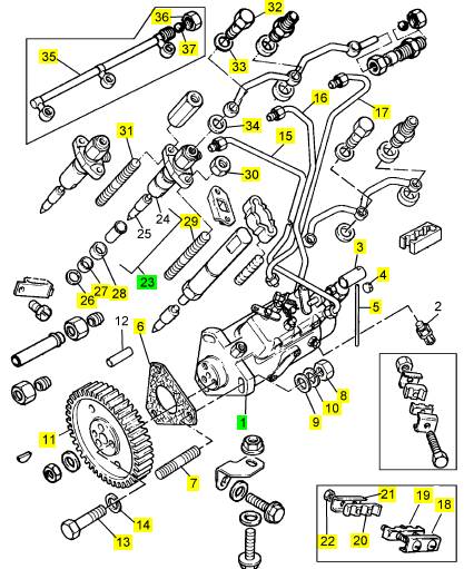
Perkins珀金斯900 3.152柴油發動機2643 B134燃料噴射泵
詳細描述
項目 零配件號碼 最新件號 描述
1 2643 B134 1 2643 B134 燃料噴射泵
3 3281 M002 1 3281 M002 套筒
4 31718104 1 31718104 密封
5 31718105 1 31718105 金屬線
6 33828112 1 3682 A008 密合墊 - 燃料的 INJ 泵
7 2217575 3 2217575 圖釘
8 0576002 3 0576002 螺帽
9 0920003 3 0920003 墊圈
10 0920053 3 0920053 墊圈
11 41115379 1 41115379 噴射泵傳動機構
11 0350010 1 0350010 合釘
11 1 燃料噴射泵傳動機構
13 0746214 3 0746214 螺旋
14 0920053 3 0920053 墊圈
15 3521 E018 1 3521 E018 燃料噴射管 號碼1 CYL。
16 3521 E019 1 3521 E019 燃料噴射管 號碼2 CYL。
17 3521 E021 1 3521 E021 燃料噴射管 號碼3 CYL。
18 38631117 1 38631117 板
19 36845115 1 36845115 夾
20 36845115 1 36845115 夾
21 36511127 1 36511127 板
22 2211401 2 2211401 螺帽
23 2645630 3 2645630 噴油器
(23) 2645630 R 3 2645630 R 噴油器 -交換
26 0921173 3 0921173 噴油器墊圈
27 33813127 3 3311 A041 密封 -噴油器
28 33813126 3 33813126 間隔器
29 2216105 3 2216105 圖釘
30 0576002 6 0576002 螺帽
31 2216105 3 2216105 圖釘
32 3218 R039 3 3218 R039 班卓琴螺拴
32 0095315 3 0095315 班卓琴螺拴 U186029K
33 2411 D007 3 2411 D007 墊圈
33 0921176 3 0921176 墊圈 U186029K
34 2411 D007 3 2411 D007 墊圈
34 0921176 3 0921176 墊圈 U186029K
35 35587359 1 35587359 回油管
36 0576111 1 0576111 螺帽
37 0020006 1 0020006 球
|
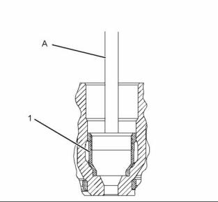
4. Tighten the nut on Tooling (A) until electronic unit injector sleeve (1) is pulled free from the cylinder head. |
|
g01043165 |
|
Illustration 17 |
|
g01393881 |
|
Illustration 16 |
|
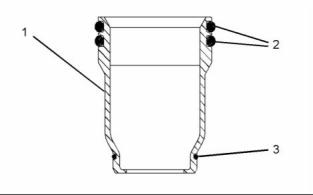
5. Remove O-ring seals (2) and O-ring seal (3) from electronic unit injector sleeve (1). |
|
i02754766 Electronic Unit Injector Sleeve - Install |
|
Installation Procedure |
|
Table 5 |
|
Required Tools |
|
Tool |
|
Part Number GE50021 GE50023 GE50024 GE50022 CV60893 |
|
Part Description Injector Sleeve Tool Tapered Brush |
|
Qty 1 |
|
g01393891 |
|
Illustration 18 |
|
A |
|
1 |
|
2. Install new O-ring seals (2) and (3) to electronic unit injector sleeve (1). |
|
B C |
|
Small Bore Brush End Brush |
|
1 |
|
1 |
|
3. Install electronic unit injector sleeve (1) to Tooling (A). |
|
Retaining Compound |
|
1 |
|
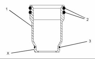
4. Apply a small continuous bead of Tooling (C) to |
|
NOTICE |
|
surface (X) of electronic unit injector sleeve (1). |
|
Keep all parts clean from contaminants. |
|
5. Lubricate O-ring seals (2) with clean engine oil. |
|
Contaminants may cause rapid wear and shortened component life. |
|
6. Position electronic unit injector sleeve (1) and Tooling (A) in the cylinder head. Use care not to damage O-ring seals (2) and (3). |
|
1. Use Tooling (B) to clean the bore in the cylinder |
|
head for the electronic unit injector sleeve. |
|
7. Use Tooling (A) and a soft faced hammer to install electronic unit injector sleeve (1) to the cylinder head. |
|
NOTICE |
|
Ensure that the electronic unit injector sleeve and the cylinder head bore are completely free of oil, dirt, and sealant debris. |
|
Note: Ensure that the electronic unit injector sleeve is properly seated in the cylinder head. |
|
This document has been printed from SPI². Not for Resale |
![]()
![]()

![]()
![]()
![]()
![]()
![]()
![]()
|
KENR6906 |
|
13 Disassembly and Assembly Section |
|
8. Install the electronic unit injectors. Refer to Disassembly and Assembly, “Electronic Unit Injector - Install”. |
|
Installation Procedure |
|
9. Fill the cooling system with coolant. Refer to Operation and Maintenance, “Cooling System Coolant - Change”. |
|
i02754770 |
|
Air Cleaner - Remove and Install |
|
g01380888 |
|
Removal Procedure |
|
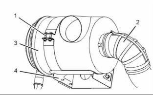
Illustration 20 |
|
Typical example |
|
NOTICE Keep all parts clean from contaminants. |
|
1. If necessary, position mounting bracket (4) on the cylinder head and install the bolts that secure the mounting bracket. Tighten theM12 bolts to a torque of 100 N·m (74 lb ft). Tighten the 3/8" bolts to a torque of 47 N·m (35 lb ft). |
|
Contaminants may cause rapid wear and shortened component life. |
|
2. Position air cleaner (3) on mounting bracket (4). Ensure the correct orientation of the air cleaner. |
|
3. Install fasteners (1). Tighten the fasteners to a torque of 55 N·m (41 lb ft). |
|
4. Connect hose (2) and tighten the hose clamp securely. |
|
i02754771 |
|
Turbocharger - Remove |
|
g01380888 |
|
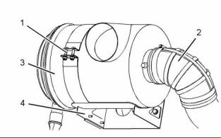
Illustration 19 |
|
Typical example |
|
Removal Procedure |
|
1. Loosen the hose clamp and disconnect hose (2). |
|
Start By: |
|
2. Remove fasteners (1) and remove air cleaner (3) from mounting bracket (4). Note the orientation of the air cleaner. |
|
a. Remove the exhaust elbow. Refer to Disassembly and Assembly, “Exhaust Elbow - Remove and Install”. |
|
3. If necessary, remove the bolts that secure mounting bracket (4) and remove the mounting bracket. |
|
NOTICE |
|
Care must be taken to ensure that fluids are contained during performance of inspection, maintenance, test- ing, adjusting and repair of the product. Be prepared to collect the fluid with suitable containers before open- ing any compartment or disassembling any compo- nent containing fluids. |
|
Dispose of all fluids according to local regulations and mandates. |
|
This document has been printed from SPI². Not for Resale |
![]()
![]()
![]()
![]()
![]()
![]()
![]()
|
14 |
|
KENR6906 |
|
Disassembly and Assembly Section |
|
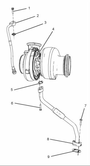
c. Remove tube assembly (2) and joint (3) from |
|
turbocharger (4). |
|
NOTICE |
|
Keep all parts clean from contaminants. |
|
3. Follow Steps 3 through 3.c in order to remove the |
|
tube assembly for the oil drain to the turbocharger. |
|
Contaminants may cause rapid wear and shortened component life. |
|
a. Remove bolts (6) and (7). b. Remove tube assembly (8). c. Remove joints (5) and (9). |
|
1. Disconnect the air hoses from the turbocharger inlet and from the turbocharger outlet. |
|
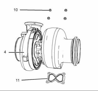
4. Attach a suitable lifting device to turbocharger (4). The weight of the turbocharger is approximately 32 kg (71 lb). |
|
g01382805 |
|
Illustration 22 |
|
Typical example |
|
5. Remove nuts (10). Use the lifting device to remove turbocharger (4) from the exhaust manifold. |
|
6. Remove gasket (11). |
|
i02754772 |
|
Turbocharger - Install |
|
g01380889 |
|
Illustration 21 |
|
Installation Procedure |
|
Typical example |
|
Table 6 |
|
2. Follow Steps 2.a through 2.c in order to remove the |
|
Required Tools Part |
|
tube assembly for the oil feed to the turbocharger. |
|
a. Disconnect tube assembly (2) from the engine oil filter base. |
|
Tool |
|
Number |
|
Part Description |
|
Qty |
|
A |
|
CV60889 |
|
Anti-Seize Compound |
|
1 |
|
b. Remove bolts (1). |
|
This document has been printed from SPI². Not for Resale |
![]()
![]()
![]()
![]()
![]()
|
KENR6906 |
|
15 Disassembly and Assembly Section |
|
NOTICE Keep all parts clean from contaminants. |
|
Contaminants may cause rapid wear and shortened component life. |
|
1. Ensure that all mating surfaces are clean and free from damage. |
|
g01382805 |
|
Illustration 23 |
|
Typical example |
|
2. Position a new gasket (11) on the exhaust manifold. |
|
3. Attach a suitable lifting device to turbocharger (4). The weight of turbocharger is approximately 32 kg (71 lb). Use the lifting device to install the turbocharger to the exhaust manifold. |
|
g01413397 |
|
Illustration 24 |
|
4. Apply Tooling (A) to the threads of the exhaust |
|
Typical example |
|
manifold studs. |
|
6. Follow Steps 6.a through 6.c in order to install the |
|
tube assembly for the oil drain to the turbocharger. |
|
5. Install nuts (10). Tighten the nuts to a torque of |
|
55 N·m (41 lb ft). |
|
a. Place a new joint (9) and tube assembly (8) in position and install bolts (7) finger tight. |
|
If a new turbocharger is installed, loosen the V-band clamps and rotate the bearing housing and the compressor housing to the correct positions. |
|
b. Position a new joint (5) between turbocharger (4) and tube assembly (8). Install bolts (6) finger tight. |
|
c. Tighten bolts (6) and (7) to a torque of 28 N·m (21 lb ft). |
|
7. Lubricate the bearings of turbocharger (4) with clean engine oil through oil inlet port (X). Rotate the shaft of the turbocharger in order to distribute the lubricant. |
|
This document has been printed from SPI². Not for Resale |