 English
 Espaol
 Franais
 阿拉伯
阿拉伯 中文
中文 Deutsch
 Italiano
 Português
 日本
日本 韓國
韓國 български
 hrvatski
 esky
esky Dansk
Dansk Nederlands
 suomi
suomi Ελληνικ
 印度
印度 norsk
norsk Polski
 Roman
Roman русский
 Svenska
Perkins珀金斯900 3.152柴油發動機41314187機油泵供應商,Perkins珀金斯900 3.152柴油發動機41314187機油泵技術價格規格咨詢服務,Perkins珀金斯900 3.152柴油發動機41314187機油泵零配件供應,Perkins珀金斯900 3.152柴油發動機41314187機油泵售后服務中心,Perkins珀金斯900 3.152柴油發動機41314187機油泵,Perkins珀金斯900 3.152柴油發動機41314187機油泵詳細的技術參數,

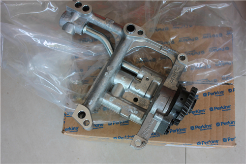
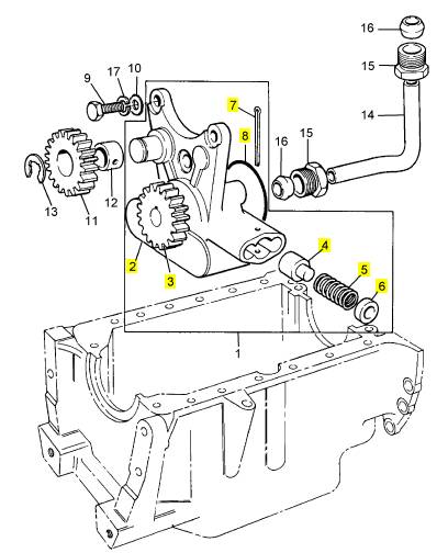
Perkins珀金斯900 3.152柴油發動機41314187機油泵
詳細描述
項目 零配件號碼 最新件號 描述
1 41314187 1 41314187 油泵
9 0746355 3 0746355 螺旋
11 41115086 1 41115086 惰輪傳動機構
13 0180831 1 0180831 夾
14 34711129 1 34711129 油管
15 33532121 2 33532121 螺帽
16 0560244 2 0560244 橄欖
17 0920053 3 0920053 墊圈
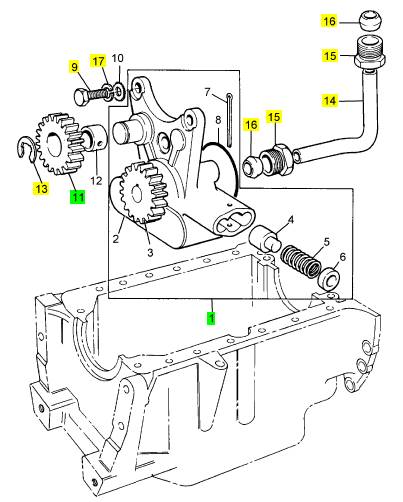
項目 零配件號碼 最新件號 描述
2 1 泵體
3 1 傳動機構
4 32712715 1 32712715 柱塞
5 31742128 1 31742128 彈簧
6 33157122 1 33157122 帽
7 0610012 1 0610012 銷
8 2415811 1 2415811 密封 - O 的圈
|
9. Loosen the nut in order to release the pressure on Tooling (B). Remove electronic unit injector clamp (1) and Tooling (B) from the electronic unit injector sleeve. |
|
10. Ensure that all of the valves are secured in place by valve springs, valve rotators and valve keepers. Rotate the crankshaft through approximately 45 degrees in order to clear the valves from the piston. Lightly strike the top of the valves with a soft faced hammer in order to ensure that the valve keepers are properly installed. |
|
End By: |
|
a. Install the electronic unit injectors. Refer to Disassembly and Assembly, “Electronic Unit Injector - Install”. |
|
i02754776 Inlet and Exhaust Valves - Remove and Install |
|
g01380893 |
|
Illustration 37 |
|
Improper assembly of parts that are spring loaded can cause bodily injury. |
|
Removal Procedure |
|
To prevent possible injury, follow the established assembly procedure and wear protective equip- ment. |
|
Table 10 |
|
Required Tools Part |
|
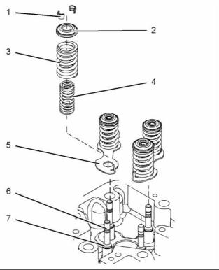
4. Install spring seats (7). |
|
Tool |
|
Number |
|
Part Description |
|
Qty |
|
A |
|
- |
|
Valve Spring Compressor |
|
1 |
|
5. Install inner valve springs (6) and outer valve |
|
springs (5). |
|
Start By: |
|
6. Position valve rotators (4) on the valve springs. |
|
a. Remove the cylinder head. Refer to Disassembly |
|
and Assembly, “Cylinder Head - Remove”. |
|
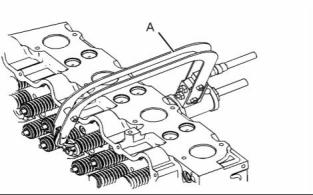
7. Position electronic unit injector clamp (1) on Tooling (B). Install Tooling (B) into the electronic unit injector sleeve. Tighten the bolt on the electronic unit injector clamp in order to secure Tooling (B). |
|
NOTICE Keep all parts clean from contaminants. |
|
Contaminants may cause rapid wear and shortened component life. |
|
The valve spring keepers can be thrown from the valve when the valve spring compressor is released. Ensure that the valve spring keepers are properly installed on the valve stem. To help prevent personal injury, keep away from the front of the valve spring keepers and valve springs during the installation of the valves. |
|
8. Tighten the nut on Tooling (B) in order to compress the valve springs. Install valve keepers (3). |
|
This document has been printed from SPI². Not for Resale |
![]()
![]()
![]()
![]()
![]()
![]()
![]()
![]()
|
22 |
|
KENR6906 |
|
Disassembly and Assembly Section |
|
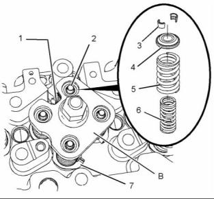
2. Carefully remove Tooling (A). 3. Remove valve rotator (2). |
|
4. Remove outer valve spring (3) and inner valve spring (4). |
|
5. Repeat Steps 1 through 4 in order to remove the remaining valve springs. |
|
6. Remove spring seats (5). |
|
7. Remove valve stem seals (7). 8. Remove valves (6) from the cylinder head. |
|
g01395727 |
|
Illustration 38 |
|
Typical example |
|
Installation Procedure |
|
Table 11 |
|
Required Tools Part |
|
Tool |
|
Number |
|
Part Description |
|
Qty |
|
A |
|
- |
|
Valve Spring Compressor |
|
1 |
|
NOTICE Keep all parts clean from contaminants. |
|
Contaminants may cause rapid wear and shortened component life. |
|
1. Inspect the valve springs for the correct length. Refer to Specifications, “Cylinder Head Valves ” for more information. |
|
Note: Valve springs must be replaced in pairs for the inlet valve or the exhaust valve of each cylinder. |
|
2. Inspect the valves. Refer to Specifications, “Cylinder Head Valves” for more information. |
|
g01392788 |
|
Illustration 39 |
|
Personal injury can result from being struck by parts propelled by a released spring force. |
|
Make sure to wear all necessary protective equip- ment. |
|
Follow the recommended procedure and use all recommended tooling to release the spring force. |
|
1. Install Tooling (A) and compress the valve springs. Remove valve keepers (1). |
|
This document has been printed from SPI². Not for Resale |
![]()
![]()
![]()
![]()
![]()
![]()
![]()
|
KENR6906 |
|
23 Disassembly and Assembly Section |
|
6. Install inner valve spring (4) and outer valve spring (3). |
|
7. Position valve rotator (2) on the valve springs. |
|
8. Use Tooling (A) to compress the valve springs. Install valve keepers (1). |
|
9. Repeat Steps 6 through 8 in order to install the remaining valve keepers. |
|
The valve spring keepers can be thrown from the valve when the valve spring compressor is released. Ensure that the valve spring keepers are properly installed on the valve stem. To help prevent personal injury, keep away from the front of the valve spring keepers and valve springs during the installation of the valves. |
|
10. Carefully remove Tooling (A). Lightly strike the top of the valve with a soft faced hammer in order to ensure that valve keepers (1) are properly seated. |
|
End By: |
|
g01392788 |
|
Illustration 40 |
|
a. Install the cylinder head. Refer to Disassembly |
|
and Assembly, “Cylinder Head - Install”. |
|
i02754778 Inlet and Exhaust Valve Guides - Remove and Install |
|
Removal Procedure |
|
Table 12 |
|
Required Tools |
|
g01395727 |
|
Illustration 41 |
|
Tool |
|
Part Number |
|
Part Description |
|
Qty |
|
Typical example |
|
A |
|
CVT0001 |
|
Valve Guide Driver |
|
1 |
|
Start By: |
|
The valve keepers can be thrown from the valve when the valve spring compressor is released. En- sure that the valve keepers are properly installed on the valve stem. To help prevent personal injury, keep away from the front of the valve keepers and valve springs during the installation of the valves. |
|
a. Remove the inlet and exhaust valves. Refer to Disassembly and Assembly, “Inlet and Exhaust Valves - Remove and Install”. |
|
NOTICE |
|
Keep all parts clean from contaminants. |
|
3. Lubricate valves (6) with clean engine oil. Install the valves to the cylinder head. |
|
Contaminants may cause rapid wear and shortened component life. |
|
4. Install valve stem seals (7) to valves (6). |
|
5. Install spring seats (5) to the cylinder head. |
|
This document has been printed from SPI². Not for Resale |